The Model Tab
The Model Tab contains a hierarchical tree of models in the scene. Multiple models can be created in one session, but a simulation should contain only one session.
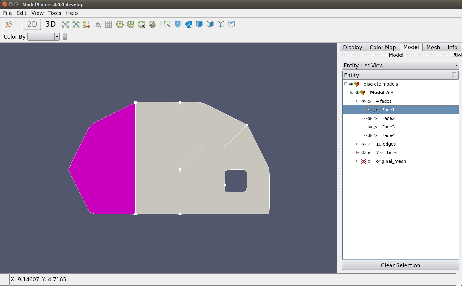
When an entity is selected, either through the entity list or the viewport, it will be highlighted. Click the “Clear Selection” button or press Esc on the keyboard to clear the selection.
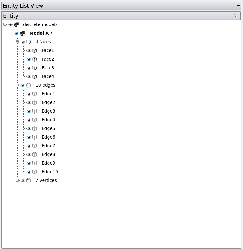
There are two different views of the model tree - entity list view and topology view, which can be switched in the dropdown menu. The entity list view groups the entities based on their types, i.e., faces, edges, vertices, meshes. The topology view, on the other hand, presents the relationships among these entities by categorizing them as parents and children.

Visibility
Clicking the  symbol toggles the visibility of the corresponding
part.
symbol toggles the visibility of the corresponding
part.
Right-clicking Content
Right clicking on any entity brings up a context menu with the operations can be applied to the specific entity. The context menu varies in different sessions as they support different operations. For example, you can create edge interactively in the polygon session but not in the discrete session.
Assign Colors
A useful operation that is shared by all the sessions is assigning colors. Colors can be assigned to a specific entity or multiple entities at the same time.
Take test2D.cmb for example. Right-click on the item in the entity tree and click on “Model Entities - Assign Colors”. You can either apply a specific color to an entity, or assign a palette to a group of entities. Here we use the default palette to color the faces.
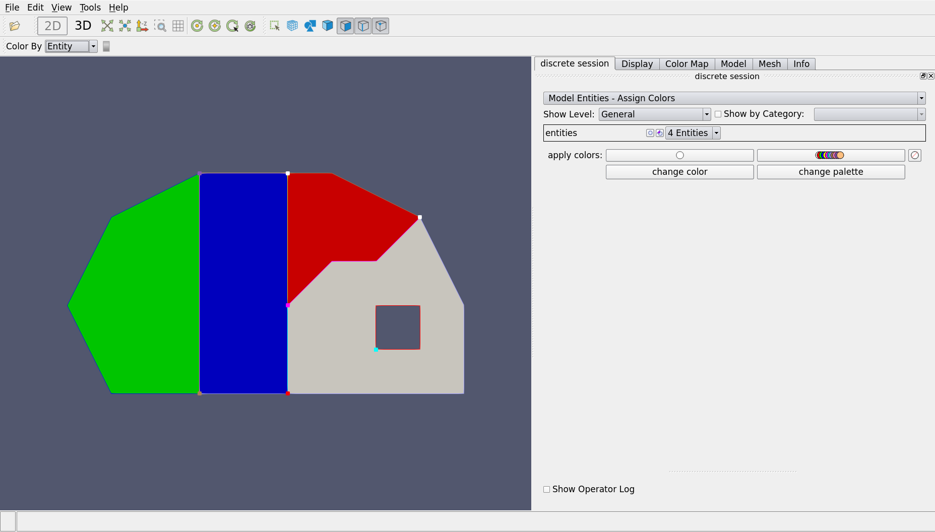
Clear selection after you apply colors. Now every face is colored uniquely. This is particularly useful in the complicated models where you cannot tell the entities apart easily. You can turn off the colors by changing “Color By Entity” to others.